
ProjectProjects · 30 min
Project: design and verify an incubator thermometer
Egg incubators are a real business across West Africa, and their heart is a temperature sensor: the eggs need about 37.5 °C. Here the sensor is a 10 k NTC thermistor (B = 3950) in a divider, next to a reference divider at exactly half the supply. You will design the fixed resistor so the sensor reads half the supply AT 37.5 °C - then use the two dividers as a bridge: a meter between their middles reads zero at the right temperature, positive when too hot, negative when too cold. That is exactly the signal a heater controller needs.
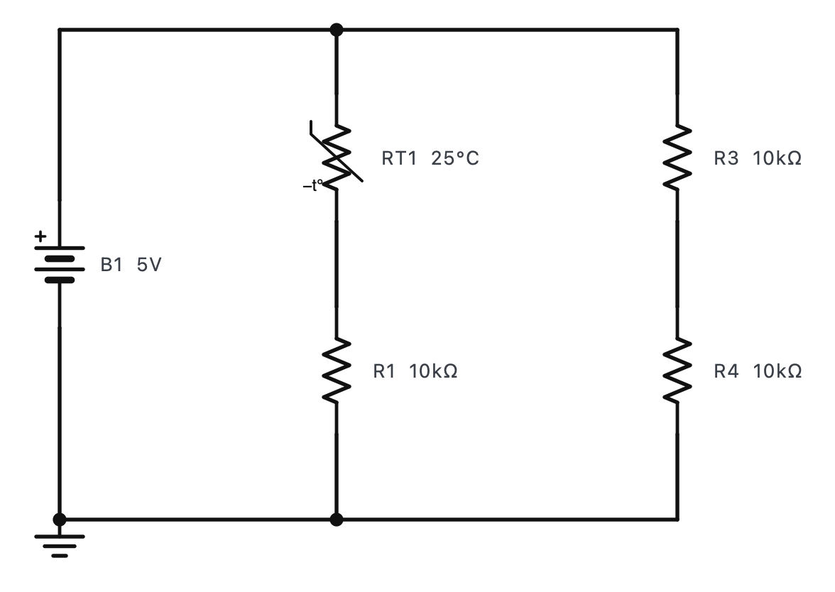
The steps
- Press RUN.RUN is on the toolbar (F5).
- Measure the sensor divider's output across R1 (V⎓): at 25 °C the NTC is 10 kΩ, equal to R1, so 2.50 V.Red on R1's top end, black on its bottom.
- Warm the thermistor to the incubator's 37.5 °C (double-click RT1). The NTC falls to 5.87 kΩ and the output rises to 3.15 V. For a controller it is best to have the middle of the range - 2.5 V - right at the working temperature.Set RT1's temperature to 37.5.
- Design: the output is half the supply when R1 equals the NTC's resistance - 5.87 kΩ at 37.5 °C. Choose a standard value: 5.9k (E96, 1 %) gives 2.51 V; 5.6k (E12) gives 2.44 V. Set R1.Double-click R1 and type 5.9k (or 5.6k).
- Now the bridge: move the meter's leads between the two middles - red on R1's top (the sensor), black on R4's top (the 2.5 V reference). It reads almost 0 V: the bridge is balanced at 37.5 °C.The meter measures the difference between the two dividers.
- Overheat the eggs a little: set RT1 to 40 °C. The bridge now reads about +0.13 V - a clear "too hot" signal (cooling below 37.5 °C would make it negative).About 0.05 V per °C around 37.5 °C.