
LessonThe voltage divider · 16 min
The voltage divider: how and why it works
Very often a circuit has the wrong voltage for the job. A 12 V battery, but the microcontroller's input only takes up to 5 V. A 5 V signal, but a 3.3 V chip. A sensor that changes its resistance, but an input that can only read a voltage. The simplest answer to all three is two resistors in series: the voltage divider. It is probably the most used circuit in electronics.
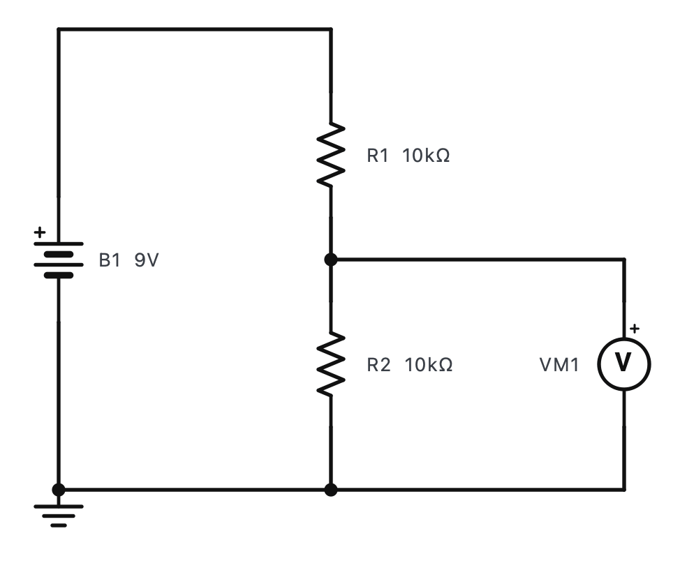
Why it works
It is just the series circuit you already know. One current flows through both resistors:
The voltage across R2 - between the middle point and 0 V - is that current times R2 (Ohm's law). Put the two together and the current cancels out:
- Vout
- the voltage across R2: between the middle point and 0 V
- Vin
- the supply across both resistors
- R1
- the top resistor (from Vin to the middle)
- R2
- the bottom resistor (from the middle to 0 V)
R1 = 20 kΩ, R2 = 10 kΩ across 9 V. What is Vout?
- Vout = 9 × 10 / (20 + 10) = 9 × 1/3.
- Vout = 3 V.
- R1 takes the other 6 V: twice the resistance, twice the voltage.
Answer: 3 V.
A 12 V lead-acid battery must be read by a 5 V Arduino input. While charging it can reach 14.4 V. With R2 = 10 kΩ, choose R1 so the input never exceeds 5 V.
- Design for the highest voltage: Vout / Vin ≤ 5 / 14.4 = 0.347.
- 0.347 = 10 k / (R1 + 10 k) → R1 + 10 k ≥ 28.8 k → R1 ≥ 18.8 kΩ.
- Choose a standard value above it with some room: 22 kΩ.
- Check: 14.4 × 10 / 32 = 4.5 V at most; a normal 12.6 V gives 3.94 V.
Answer: R1 = 22 kΩ, R2 = 10 kΩ.
Make both resistors 10× smaller: Vout stays the same, the wasted power grows 10×.
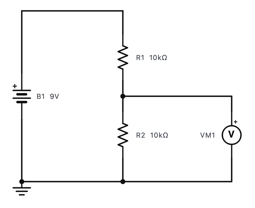
The curve is not a straight line: Vout climbs quickly while R2 is small compared with R1, then levels off towards Vin. That shape matters for sensors - the divider is most sensitive where R2 is close to R1.
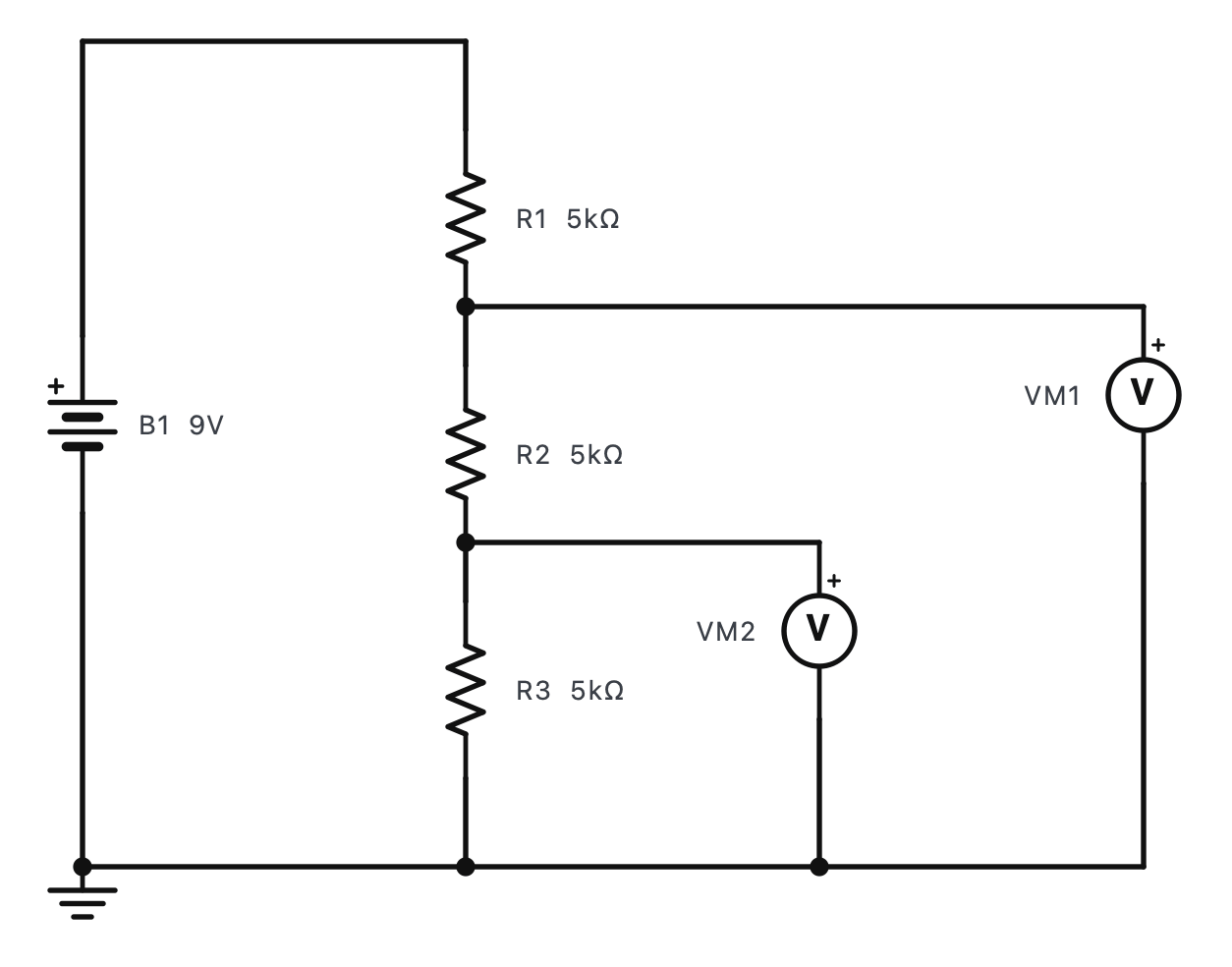
More than two resistors
Practice 1R1 = 4.7 kΩ, R2 = 4.7 kΩ, Vin = 5 V. What is Vout?
Hint
Equal resistors share equally.
Show the answer
Answer: 2.5 V
5 × 4.7 / (4.7 + 4.7) = 2.5 V.
Practice 2R1 = 10 kΩ, R2 = 40 kΩ across 10 V. Vout?
Show the answer
Answer: 8 V
10 × 40 / 50 = 8 V.
Practice 3Which change makes Vout larger?
- A bigger R1
- A bigger R2
- Both resistors 10× smaller
- A smaller supply
Show the answer
Answer: B. A bigger R2
Vout is R2's share: a bigger R2 takes a bigger share.
Challenge 4You need exactly 1/4 of a 20 V supply and have R2 = 3.3 kΩ. What R1 do you need?
Hint
R2 / (R1 + R2) = 1/4, so R1 = 3 × R2.
Show the answer
Answer: 9900 Ω
R1 + R2 = 4 × R2 → R1 = 3 × 3.3 k = 9.9 kΩ (10 kΩ from the E12 series gives 4.96 V instead of 5 V).
Challenge 5A ladder of 1 kΩ (top), 2 kΩ and 3 kΩ (bottom) is across 12 V. What is the voltage at the junction between the 1 kΩ and the 2 kΩ?
Hint
The resistance below that point is 2 + 3 = 5 kΩ out of 6 kΩ.
Show the answer
Answer: 10 V
12 × 5 / 6 = 10 V. (The lower tap is at 12 × 3 / 6 = 6 V.)