
LessonThe voltage divider · 17 min
Battery monitors, level shifting and bias
Dividers do far more than read sensors. This lecture follows three jobs you will meet in nearly every product: measuring a battery, connecting a 5 V chip to a 3.3 V one, and setting the working point of a transistor or regulator.
1. The battery monitor
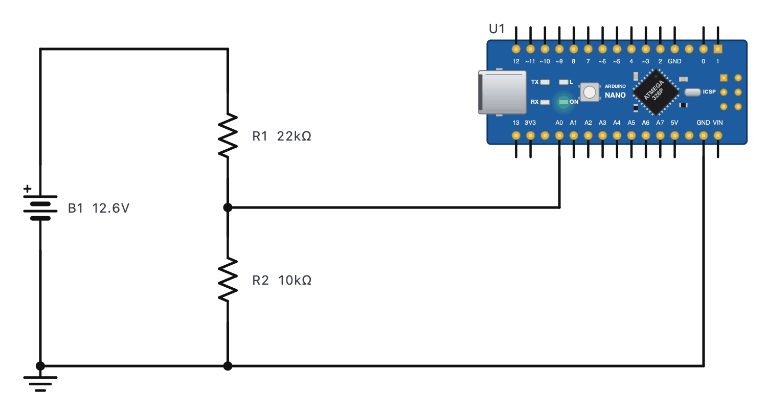
- Find the worst-case input. A "12 V" lead-acid battery is 12.7 V full, 14.4 V while charging and maybe 15 V if a charger fails. Design for 15 V.
- Choose the ratio so the worst case stays under the ADC's limit (5 V here): ratio ≤ 5 / 15 = 0.333. 22 k / 10 k gives 0.3125: 15 V → 4.69 V.
- Choose the size: 10 k - 100 k range. Small enough for the ADC (see the loading lecture), big enough not to drain the battery: 12.6 V / 32 kΩ = 0.39 mA.
- Convert back in software.
- N
- the ADC reading (0 - 1023 on a 10-bit Arduino)
- Vref
- the ADC's reference: 5 V on an Uno or Nano
- (R1 + R2) / R2
- the divider's ratio turned upside down: 32 / 10 = 3.2
With the 22 k / 10 k divider, the Nano reads N = 806. What is the battery voltage?
- VA0 = 806 × 5 / 1023 = 3.939 V.
- Vbat = 3.939 × 3.2 = 12.6 V.
Answer: 12.6 V - a fully charged lead-acid battery at rest.
2. Level shifting: 5 V into 3.3 V
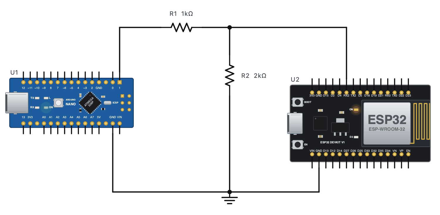
A 3.3 V chip such as the ESP32 or a Raspberry Pi can be damaged by 5 V on its pins. For a signal going one way, from the 5 V side to the 3.3 V side, a divider is the cheapest fix: 1 k / 2 k, 10 k / 20 k or 1.8 k / 3.3 k all give about 3.3 V. The other direction usually needs nothing: 3.3 V is high enough to count as a HIGH for most 5 V inputs.
3. Bias and feedback: a divider sets a working point
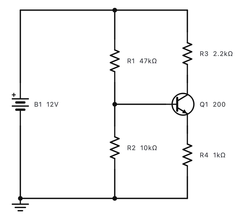
- Transistor amplifiers use a divider (like R1 / R2 above) to hold the base at a steady voltage.
- Adjustable regulators: an LM317 holds 1.25 V across its feedback resistor, so a divider sets the output: Vout = 1.25 × (1 + R2 / R1). The little trimmer on a cheap LM2596 buck module is the bottom half of such a feedback divider.
- Thresholds: a comparator switching a low-battery alarm or a street light compares the sensor's voltage with a reference made by another divider.
Where you meet it
Read the battery and the panel through dividers to decide when to charge.
Battery gauges and charger detection start with dividers.
Level shifting for GPS, Bluetooth and Wi-Fi modules.
Every adjustable regulator's output is set by a feedback divider.
Practice 1A 22 k / 10 k divider reads a battery. A0 shows 4.2 V. What is the battery voltage?
Show the answer
Answer: 13.44 V
4.2 × 32 / 10 = 13.44 V.
Practice 2A 10 k / 20 k level shifter (10 k on top) gets a 5 V signal. What reaches the 3.3 V pin?
Show the answer
Answer: 3.333 V
5 × 20 / 30 = 3.33 V.
Practice 3An LM317 has R1 = 240 Ω and R2 = 720 Ω. What is its output voltage?
Hint
Vout = 1.25 × (1 + R2 / R1).
Show the answer
Answer: 5 V
1.25 × (1 + 3) = 5.0 V.
Challenge 4You must read a 24 V battery bank (up to 29 V when charging) with a 3.3 V ESP32 input. With R2 = 10 kΩ, what is the smallest R1 that keeps the pin at or below 3.0 V at 29 V?
Hint
R2 / (R1 + R2) ≤ 3.0 / 29.
Show the answer
Answer: 86667 Ω
R1 + R2 ≥ 10 k × 29 / 3 = 96.7 kΩ, so R1 ≥ 86.7 kΩ. Choose 100 kΩ: 29 V → 2.64 V.
Challenge 5With 100 k / 10 k on that 24 V bank, the ESP32's 12-bit ADC (0 - 4095 for 0 - 3.3 V) reads 2730. What is the bank's voltage?
Hint
Vpin = N × 3.3 / 4095, then × 110 / 10.
Show the answer
Answer: 24.2 V
Vpin = 2730 × 3.3 / 4095 = 2.200 V. Vbank = 2.2 × 11 = 24.2 V. (A real ESP32 ADC is not very linear - calibrate it.)