
LabThe voltage divider · 15 min
Lab: light and temperature sensors
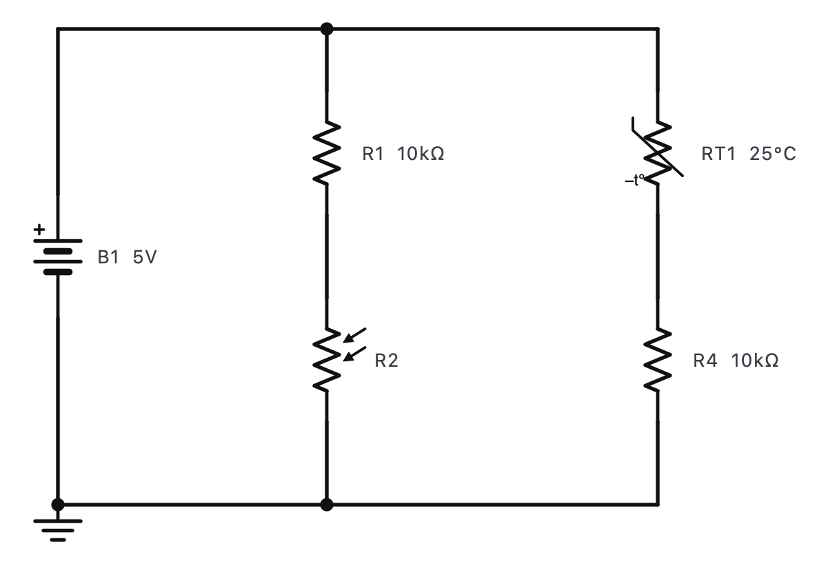
Two sensor dividers on one 5 V supply: an LDR (light) and an NTC thermistor (temperature). Measure each, change the light and the temperature, and watch the voltage follow.
The steps
- Press RUN.RUN is on the toolbar (F5).
- Measure the LDR divider: the multimeter on V⎓ across the LDR R2 (red on its top, black on its bottom). In normal light the LDR is about 10 kΩ, equal to R1: 2.5 V.The output of this divider is R2's top end.
- Cover the LDR: click it once (each click makes it darker). Its resistance jumps to about 100 kΩ and Vout rises to about 4.5 V. Dark → high voltage.Click on the LDR itself while the circuit runs.
- Now the thermometer: move the leads across R4 (the fixed 10 kΩ under the thermistor). At 25 °C the NTC is also 10 kΩ: 2.5 V.Delete the lead wires and wire them to R4's ends.
- Warm the thermistor to 40 °C (double-click RT1 and set its temperature, or click its right half to warm it 2 °C at a time). Its resistance falls to 5.3 kΩ and Vout rises to about 3.27 V.NTC: Negative Temperature Coefficient - warmer means less resistance.