
LessonUsing a multimeter · 13 min
Measuring resistance and continuity
On Ω the meter becomes a tiny power source: it pushes a small known current through whatever is between its leads and measures the voltage that results. That is why resistance is measured with the circuit switched off - any other voltage would upset the reading (in the simulator, the meter then shows "- - - -").
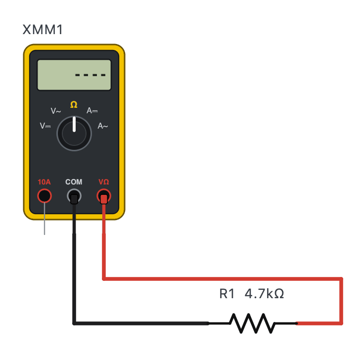
The in-circuit trap
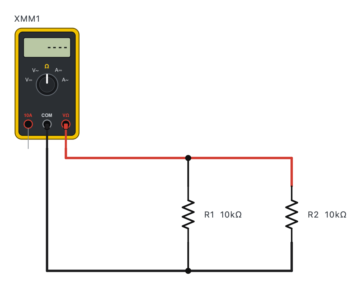
The meter measures everything connected between its probes. In a circuit, other parts almost always form parallel paths, so the reading comes out lower than the part's real value. To measure a part properly, unsolder (lift) at least one of its legs.
- Power off, and let big capacitors discharge first.
- Lift one leg of the part, or measure it before soldering.
- Do not hold both probe tips: your body (100 kΩ or more) adds a parallel path - it matters when measuring high values.
- Short the probes together first for small values: the leads themselves read 0.1 - 0.3 Ω; subtract that.
Continuity: the beeper
Continuity mode beeps when the resistance between the probes is very low (below roughly 30 - 50 Ω, depending on the meter). You do not need the number - only "joined or not". It is the quickest fault-finding tool there is.
What to check with continuity
A good fuse beeps; a blown one reads OL.
Beep from one end of each core to the other to find a break - or to identify which core is which.
Beep when on, OL when off.
Before the first power-up, check there is NO beep between the supply and GND: a solder bridge found now costs nothing; found with power on, it costs parts.
Practice 1A 10 kΩ resistor is measured in-circuit with a 2.2 kΩ resistor in parallel with it. What does the meter read?
Show the answer
Answer: 1803 Ω
10 × 2.2 / 12.2 = 1.80 kΩ.
Practice 2A fuse reads OL on the continuity setting. The fuse is:
- Good
- Blown (open)
- Shorted
- The wrong rating
Show the answer
Answer: B. Blown (open)
OL = no path: the fuse wire has melted.
Practice 3Your probes shorted together read 0.2 Ω. A cable core then reads 0.7 Ω. What is the core's resistance?
Show the answer
Answer: 0.5 Ω
0.7 − 0.2 = 0.5 Ω.
Challenge 4A potentiometer's two outer pins read 10 kΩ. One outer pin to the wiper reads 3.2 kΩ. What does the other outer pin to the wiper read?
Hint
The wiper divides the track into two parts that add up to the whole.
Show the answer
Answer: 6800 Ω
10 − 3.2 = 6.8 kΩ.